


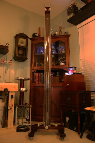
I Just finished the assembly of my DRSSTC. I have just started to fine tune the coupling and and dialing in the primary tap. This is it's first run.
Tuesday, January 24, 2012
Saturday, January 8, 2011
Plasma water electrolysis
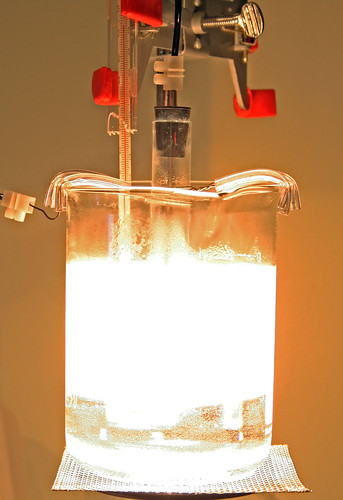
This is a simple calorimeteric device I built to help the determination of the heating power of a plasma water electrolysis (Mizuno - like experiment). I confirm that in this experiment, the heating power of the electrolysis is greater than the electrical power injected in the device. The excess energy increases as the electrolysis voltage is increased from 200 V up to 350 V (400 W input). The excess energy may be as high as 120 W. The abnormal excess heat shown here exceeds 120 watts without taking into account the gas formation and also the luminous radiation. This power is therefore definitely meaningful. I did not find in this device any classical explanation for this thermal effect and I'm examining the possibility of less classical explanations. The initial purpose of these experiments were to investigate the potential of a simple experimental device in order to confirm the results obtained by T. Mizuno. I think that this first step is obtained and that I can say that ratios between energies out and in (COP) of 1.3 and 1.4 have been reached with a satisfactory reproducibility. In the next step I will try to explain this phenomenon in order to increase the COP performances. So in conclusion this is what I did to see if I could get more energy out of this device than what I put in. No Im not a Scientest I only play one on the internet.
New Year and new goals.
I've been off the back on posting so I'm going to try and post at least once a month. I've been working on lots of new projects and have made some interesting findings and would like to share as much as possible. The main thrust of my studies have been in the area of alternative energy sources. This area is extremely controversial and I have attempted to stick to the science. I truly believe that solutions to our energy crisis could be found by a home experimenter. I'm not saying that will be me but I feel if I don't try to understand I'm doomed to never know. On my journey to understand I have come to learn things I never thought I would need to and I have found that learning for me is something that I truly enjoy and need. I have made what for me were amazing findings during late nights spent watching magnets spin in mid air and watching the star like glow of a high temperature electrolysis experiment. These I would like to share with you.
Jiffycoil
Thursday, May 13, 2010
Tiny Tiny Tesla coil
I was cleaning the Lab and had a few parts that were laying around that gave me an idea. I could take a small plastic wire spool, a dead ink pen, a few bent brass bolts, a few tiny low powered capacitors and a few bits of different wire and build a Tiny Tesla coil. Wow big surprise Huh? After about and hour of work and a bunch of McGivering I ended up with this. It works really well and I have more fun with it than I do with many of my larger coils. What next? A series of ultra tiny tesla coils? Twist my arm.


Friday, April 16, 2010
Wireless Electricity
This is based on a project by Marko at 4hv,org. I laidout the PCB in Express PCB.
"The idea behind the project was to create a small tabletop demonstrator of magnetically coupled wireless power transfer, resembling a miniature version of the MIT 'witricity' device. The goal was to keep the circuit simple with easily obtainable parts, and to keep voltage and power levels low so the device is safe for handling and doesn't require special methods of cooling.
The basic idea is to feed a parallel LC tank circuit from an AC voltage source at it's resonant frequency, which allows large reactive current to circulate in the circuit while only real power is being drawn from the source. This sets up a large alternating magnetic field in the inductor, which is designed as a single conductive loop in this case.
Now, another LC tank with load attached is brought in proximity to the excited LC circuit, significant amounts of power can be transferred via weak magnetic coupling between them. This is because AC current itself in the transmitting loop is very large, and inductive reactance of the receiver loop is canceled out by the capacitor.
For a practical device, the AC voltage source had to be substituted with an appropriate oscillator, which would take feedback from the tank circuit itself and hence always drive it at it's resonant frequency.
The circuit of choice was a slightly modified royer oscillator, such as popularly used in CCFL inverters and for flyback drivers.
Input voltage was limited to 15V for safety and because the circuit tends to become unstable at higher voltages."
Subscribe to:
Posts (Atom)